Increase Operator Support via Integrated Platform Management System Automation to Support the Internal Battle
Introduction
Frigates are designed to continue with their war fighting task even after having suffered serious internal damage from external threats such as gunfire, missiles and mines. Serious damage may demand a lot of activity from the ship’s crew before the ship has retrieved its capability to its fullest extent. Fires need to be extinguished, leakages to be isolated or blocked, smoke and water need to be removed and technical systems need to be repaired. During all this damage limiting activity the commanding officer requires the maximum possible war fighting capability to be available. He states his required capabilities in the Command Aim: What is the current task for the ship and in what priority should the ships functions be retained or recovered? All activities on board should be directed based on this Command Aim
Battle Damage Repair (BDR) process
To understand how the crew can be supported best an analyses of the Battle Damage Repair (BDR) process is made.
The BDR process can be divided in the following tasks:
Gathering information (through communication and plotting),
Assessing information (to obtain situational awareness),
Decision making and
Acting.
As illustrated in figure 2, these actions are performed in a continuous cycle.
In order to understand the results of the task analysis first the generic tasks and how these are performed are described. Subsequently an estimate is given of the time spent on these tasks by the BDR team.
Gathering information
The information on the extent of damage after a hit of the ship by external projectiles is gathered by executing a physical ‘blanket search’ by the crew of the ship while in parallel the Integrated Platform Management System (IPMS) generates alarms that indicate a problem.
With the ‘blanket search’, every single compartment is physically checked by teams of two crew members that subsequently vocally report the damage through the BDR organization following the vocally report the damage through the BDR organization. This means that information on the damage is communicated through several levels.
Damage related to leakages and fires is first gathered and plotted on the incident board by a plotter. Subsequently this information is verbally communicated to all other stations, through the plotter over a Damage Control (DC) communication line. At these stations this information is plotted again on the incident board. Therefore, the quality of the information on the incident board strongly depends on the quality of communication that takes place under stress. It is clear that the information on the incident boards often is out of date, incomplete and inaccurate. It’s also evident that this communication and plotting process is very manpower intensive.
Damage related to mechanical and electrical systems is communicated to the Mechanical and Electrical Officer respectively. These officers gather this information on their personal state board and subsequently report their top priorities to the NBCD Officer and other team members that need to know. Again the gathering of information is manpower intensive. The information on the incident boards is often inconsistent, of a low quality and not available for the whole team.
Assessing information
All management need to assess the incoming information to obtain situational awareness. Although not always consistent and often inaccurate the DC incident boards provide a good means to obtain situational awareness on DC incidents.
The availability of technical systems, although often indirectly available in the Integrated Platform Management
System (IPMS) is not presented in any way to the management, other than scrolling through the enormous amount of MIMIC presentations in the IPMS. Therefore every team member acts on the information he or she has available for him- or herself on the personal state board. It needs no explanation that the situational awareness of the team is not consistent and often inaccurate. In order to overcome this operators and managers maintain handwritten lists of system availability that are stuck to the Ship Control Centre (SCC) wall to release information for the whole team.
Decision Making
Because information is not presented in a structured way and because information has to be gathered from multiple sources that do not communicate related information simultaneously, only very limited time is available for decision making. What makes it even more challenging is that often decisions are requested from the lower hierarchical levels but the information required to take the right decisions is not readily available. This has two effects: The quality of the decisions is not optimal and the time spent on decision making is very limited: estimated between 10 and 30% of the available time.
Acting comprises:
Execution of operator sequences determined in the analysis and
Deployment of Battle Damage Repair teams (to fight fires, stop leakages and repair systems).
The execution of operator sequences under stress often causes errors and takes the focus away from sufficient communication and maintaining situational awareness. Therefore officers are all supported by an operator. The execution of repetitive operator sequences requires significant manpower and the high workload of the operator causes operator errors. The operators are executing operator sequences (that can be automated) 70% of their time spending their remaining time on communicating their actions to the SCC officers.
The deployment of Battle Damage Repair teams takes the reverse route of the information on the incidents. Due to the overload of communication lines often the deployment of these teams is delayed as officers are awaiting confirmation of their priorities and thus where to send the limited amount of resources. The time spent on ordering the deployment of Battle Damage Repair teams is included in the tasks decision making and communication (gathering of information taking place in both directions).
Conclusions of task analysis
To build up the desired awareness of the overall damage situation the management of the Damage Control
Organization spends approximately 50% of her time on communication. Communication between the scene of an incident and the Ships Control Centre may take place over as many as 5 levels. This is time consuming and still can result in an incomplete picture. The Damage Control Organization requires a system that achieves reduction in the amount of communication and related workload and provides a consistent situational awareness across the whole organization.
In order to make the right decisions, the technical management in the Ships Control Centre (the NBCD officer, the mechanical officer and the electrical officer) requires a good overall awareness of the situation. On today’s ships, these officers rely for 80% of their information on communication even though the information on the status of all technical systems is available in the IPMS. The technical management in the SCC requires a system that provides a clear, commonly accessible, overall picture of the technical systems and their status in relation to the Command
Aim.
The operators in the Ships Control Centre experience a high workload. This is partly caused due to the time required for repetitive operator sequences and the high communication load. A system is required that automates repetitive sequences and assists the operator in analyzing the effect of alarms, can reduce the workload and increase the effectiveness of the operator.
Integrated Platform Management System (IPMS) support functions
According to the above task analysis and conclusions the IPMS should support the operator in the following:
Reduce communication and make information available to all parties.
Present the information in a clear and understandable way for each level in BDR organization.
Reduce workload of the operators by automate repetitive actions.
How can the IPMS support the operator achieving the above conclusions? The following three additional support functions are developed by Imtech Marine, in close cooperation with the Royal Netherlands Navy, to support the management of the internal battle and fulfil the requirements that follow from the task analysis above.
Fire Fighting and Damage Control System (FFDC)
The Fire Fighting and Damage Control System is aimed to achieve reduction in the amount of communication and related workload and provision of a consistent situational awareness across the Damage Control organization.
Design of the FFDC system
In order to meet the requirements an electronic plotting board was designed. This plotting board has two main
Human Machine Interface (HMI) parts. The first part (left) is a plotter screen. Through this plotter screen the operator can enter information. A typical FFDC plotter screen is illustrated in figure 3.
The second part (right) is an overview screen. This overview screen provides an overview of the plotted damage on a complete ships plan and displays the damage information similarly to the conventional plot board. The information entered through the plotter screen is subsequently stored on the FFDC computer system, consisting of a client server configuration. This system ensures entered information is distributed to all electronic incident boards across the ship, ensuring the available information is consistent across the ship and no communication is required to distribute information .
The design of the FFDC system includes a configurable interface to ship systems. Information of fire detectors, doors, hatches, etc is provided by the IPMS system of Imtech Marine.
From every FFDC position it is possible to plot symbols like fire, boundary cooling and smoke boundaries. Every type of symbol has its own specific properties and stages. The plot symbols are electronic version of the symbols defined in the Royal Netherlands Navy standard KN 15750. This makes it easy for personnel on board to switch from the conventional incident board (where the plotter draws the symbols by hand) to the FFDC HMI.
Selecting a plot symbol from the library and dragging it into a compartment is a user-friendly approach for placing a symbol on a desired spot. Subsequently, the state and time of the symbol become automatically available on all
FFDC stations. In the FFDC HMI all kinds of features have been implemented to meet requirements for optimal control of the application, particularly under stress conditions.
In the FFDC overview screen it is possible to present all kinds of important information for BDR. The FFDC HMI stores this information in layers. It is important that at any given time only the relevant and required information is presented; other information layers can be hidden.
Examples of information layers are:
A- and B-type fire wall layer;
Citadel information layer;
Safety and fire equipment layer;
Hazardous equipment layer.
A free scribble option of the FFDC HMI gives the operator the possibility to draw (and share) lines (e.g. attack and evaluation routes) and to place texts in the Deck view window of the FFDC plotter screen.
The FFDC design promises to achieve increased situational awareness with reduced communication.
It proofed that it really reduces operator workload and it allowed for crew reduction when the FFDC system was implemented on board a number of Royal Netherlands Navy ships, such as the Patrol Vessel of Royal Netherland Navy.
Additional Functionality
In the near future, multi-touch monitors may combine the plotter input function with a deck overview. Today, the multi-monitor / multi-touch technology has improved enough to be used as alternative for the plotter input functions while simultaneously providing a deck overview. It is expected that this reduces the workload of plotters even further, enabling the reduction of the amount of plotters.
Other near future options to reduce the workload on board and to use manpower more efficiently are:
The integration of wireless connected handheld computers. These handhelds will allow team leaders to directly enter information from the scene of the incident into the FFDC system, while the FFDC system ensures that information is shared almost instantaneously. This development would render plotters redundant;
Integration of the onboard CCTV system into the FFDC system. This promises to give personnel at the Ship Control Centre immediate access to visual information about the scene of the incident. It is a fast and safe alternative for sending personnel to that area that may be better used to correct the problem rather than to obtain information about the problem;
Information wall in the Ships Control Centre
The information wall in the Ships Control Centre is designed to provide a clear, commonly accessible, overall picture of the technical systems and their status in relation to the Command Aim. It consists of a number of screens, the design of which will be described here.
Design of the information wall
The SCC does not manage calamities with the combat systems. However the functional dependency between combat systems and platform systems and the potential relationship between damage such as fires and floods and system defects, demands presentation of combat system status in the SCC. In fact in many damage situations the combat system defects take priority over platform system defects and damage. The SCC management effort should then be focused on supporting the repair of combat systems. Figure 4 shows the overview of combat system availability that allows the SCC team to relate their efforts to the combat system status. This picture is built up in the Combat Management System and its design is already available in current Royal Netherlands Navy ships.
The platform systems typically consist of two important system parts. The platform system generation system (electrical generator, diesel engine, pump and compressor) and the distribution system. Due to their difference in nature and location they are represented in two views as illustrated in figure 5. These pictures will be built up from system status information available in IPMS. The FFDC workgroup is currently undertaking the development of these views.
In order to relate system defects to the Command Aim the NBCD Officer deduces the required system capability
from the Command Aim. This information is entered into the Command Aim view illustrated in figure 6.
Additionally in this view the actual platform system availability as built up from IPMS status information is
presented. When the required system capability is not met that platform system hampers the Command Aim. This is represented in the Command Aim view by a red status block. This overview helps the SCC team to determine priorities of its activities. In essence the information wall provides a joint situational awareness for the SCC team.
Future development
In future status information on visual observations, progress on repair and Estimated Time Back Online (ETBOL) can potentially be entered from the scene of the incident using handhelds. Including this information in the views described above, all information flow can be achieved by digital means, ensuring high quality of information and minimized workload.
BDR Procedures (repetitive operator sequences)
A system to program and execute BDR procedures is under development that can automate repetitive sequences and assist the operator in analyzing the effect of alarms, thus reducing workload and increasing the effectiveness of the operator.
In general, it is not too difficult to automate functions as demonstrated by the Integrated Platform Management
System (IPMS). However, such functionality has to be specified in advance as it has to be known in the engineering phase when it is configured or hard coded. This is a serious drawback as the definition of procedures depend heavily on experience which is obtained over the life cycle of a ship. This insight initated the requirement of the Royal
Netherlands Navy for an Advice Builder, an application that enables designers as well as operators to assemble procedures during the engineering phase and during the time that the ship is in service.
The Imtech IPMS used on modern ships of the Royal Netherlands Navy already includes ‘Apps’ that allow externalsystems to give commands to virtually any ship system that is monitored and controlled by means of the IPMS. This resulted in an application comprising four parts:
an Advisory Module in the IPMS filled with the available advises;
a dedicated HMI interface to the operator;
‘App’ within the IPMS responsible for executing the triggers and steps;
an Advice Builder to be used for configuration of the advises.
The Advisory Module is supporting multiple advisory functions. A number of possible advisory functions are listed
below:
Propulsion.
Steering.
Electrical isolation.
Compartment isolation.
Engine room isolation (ready for Halon release).
• Seawater leakage.
The Advisory Module resembles a database filled with advises that have been designed, and subsequently tested, on shore-based facilities. The ‘App’ within the IPMS will start a specific advice once the pre-defined condition of that advice is met.
The advices are presented in a dedicated IPMS advisory HMI and can be configured for three execution modes:
Auto: advice steps which can be processed by the IPMS are executed without confirmation of the user.
Confirm: advice steps which can be processed by the IPMS are only executed with the explicit
confirmation of the user.
Manual: advice steps are only available as a check mark list. Applicable IPMS actions shall not be
executed.
Figure 7 shows the HMI of the IPMS Advisory Module. The mid section of the advisory HMI depict the active advices and the status of the advices. The particular advice steps can be divided over four advice task groups: “Operator” actions, “IPMS” actions, “SCC” actions and “Local” actions. The advice task groups are preseted in the bottom part of the IPMS advisory HMI including buttons for confirmation and detailed information of a step.
Although far from being a complete BDR Procedure system, the test configuration already shows much promise. It is easy to use, gives an excellent idea of what is going on, simplifies operator actions and certainly seems to be able to unburden an operator in stressfull situations. The first impression is that such functionality will indeed allow a significant reduction of the manning requirement for BDR operations but also support unmanned SCC operation..
CONCLUSIONS
A radical reduction of the manning of naval vessels requires radical measures in the field of BDR. Each and every task, even each and every action of the crew involved in BDR should be analyzed and assessed to verify whether or not it is really relevant and that there is really no alternative for the human operator.
The human operator is used to gather information, to convert the information to obtain a suited awareness of the situation, to share the information with others and to act jointly to stabilize the situation and, if possible, to correct the situation. On each of these tasks, advanced automation applications integrated in the PMS offer alternatives often with a speed and quality that cannot be matched by the human operator.
However, the desired IPMS system is an integration of a wide variety of subsystems and modules within other automation systems. This implies a new approach towards the design of such components to the extent that they are able to share relevant information, also with combat systems, and act upon commands from BDR operators.
A really integrated IPMS system with many autonomously operating components promises to do more than allowing fewer operators to battle some emergency. In principle, it promises a much faster and better awareness of the situation and therefore a faster and better response. In addition, it implies less exposure of sailors to hazardous situations.
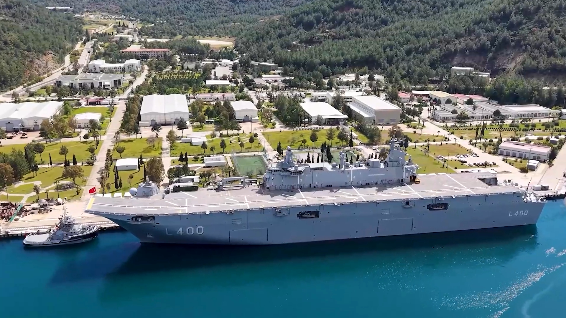
Showcase OPV Royal Netherlands Navy
The Royal Netherlands Navy is operating her frigate size Oceangoing Patrol Vessel across the world with only a crew of 50 people.
This is achieved by highly automated systems and limiting the requirements on fight through capability. For its future frigates the RNLN aims to maintain the manning level of the OPV and simultaneously increase the fight through capability to the level of traditional frigates.
By installing Imtech Marine IPMS with the support functions discribed in this paper the Royal Netherlands
Navy, in cooperation with Imtech Marine, was able to reduce their crew substantually in the BDR organization.
References
1 Advanced PMS functionality in the Royal Netherlands Navy: Automation to support the internal
battle, INEC 2012